The first task was to make some drawings of the main chassis rails. The
only drawings I could find were in the Land Rover service manual (AKA
The Green Bible). Although there are quite a few useful dimensions they
are aimed more towards repairing or straightening an existing chassis.
Out came the long straight edge, tape measure and CAD package.
Unfortunately I lost some of my earlier photos when a hard drive
failed. Yes, I know - I should have made backups.
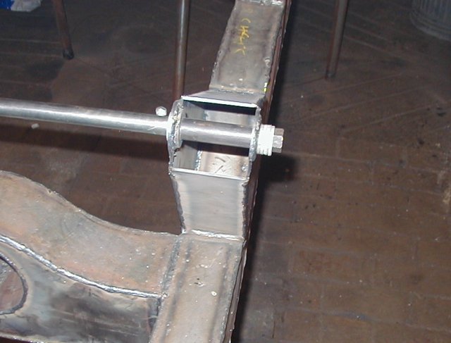
 As my plasma cutter is only 2.5 metres long and the
chassis is 3.4 metres long the rails had to be joined in the
middle. I used a V joint rather than a butt joint because it is stronger
and it is easier to line up. The welds are not pretty but they are
strong. My welding is normally better than this but I just can't get the
hang of using CO2 and my Argoshield has run out.
As my plasma cutter is only 2.5 metres long and the
chassis is 3.4 metres long the rails had to be joined in the
middle. I used a V joint rather than a butt joint because it is stronger
and it is easier to line up. The welds are not pretty but they are
strong. My welding is normally better than this but I just can't get the
hang of using CO2 and my Argoshield has run out.
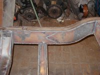
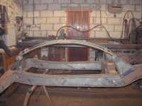
This is the chassis with most of the crossmembers in place.
The front crossmember is completely non-standard because I had to move
it forwards by about 6" to clear the Range Rover power steering box. You
can also see a rectangular hole in the rear crossmember. This is to take
a snatch block for the mid-mounted winch (see the winchpage
for more details). The rear crossmember is also a less complicated
design and made out of 3mm steel, rather than the original 2mm.

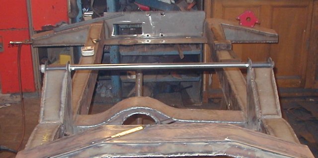
Here is how I made sure the spring mounts came out in exactly the right
place. A steel bar goes right though both mounts and prevents them from
moving when they are welded
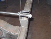
There is a tube between the mount side plates to make sure they don't
move.
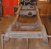
The spring mounts are 2" higher, like the long wheel base military
version. With military shackles and parabolic springs there appears to
be a frightening amount of space between the spring and the chassis. I
hope this closes up a bit when I put some weight on it!
home