Materials:
Beam
40x40 box section, 450mm long
Saddle
2 off 50x50x6 angle, 80mm long or box section that is a good fit on
beam
Hoop
10mm round or square bar, 200mm long
Handle
Bitmap image DXF
drawing
25 x 5 strip, 100mm long
12mm round bar, 60mm long
End plates
Bitmap image DXF
drawing
2 off 80 x 6 strip, 85mm long
Threaded bar
M16 threaded bar, 500mm long.
3 off M16 nuts
Full drawing: Bitmap image DXF drawing
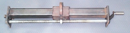
Construction:
Wrap a couple of layers of thick paper or one layer of thin card around
the beam.
Place the two pieces of angle over the wrapped bar to form a box section.
They will form the saddle. You will need to grind the edges of the angle
where they meet to make them a tight fit on the beam. Tack weld the two
pieces of angle together and slide them off the box. Remove the paper and
check the saddle slides easily on the beam without too much play. Fully
weld the pieces together and check again.
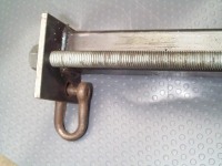
Mark out one end plate, clamp the two together and drill the 13mm and 16mm holes.
Place one end plate flat on a heat proof surface. Slide the saddle over
the box and place them on the plate. Screw one of the nuts approx 45mm
on to the threaded bar and place the threaded bar in the 16mm hole, with
the nut touching the saddle. Place the other end plate on top of the assembly
to hold it together. Placing a weight on top helps stability. Another pair
of hands are useful at this stage.
Tack weld the nut to the saddle. Turn the threaded bar until the saddle
is approx 10mm off the lower end plate and tack weld the box section to
the end plate. Wind the saddle to the other end of the bar, turn the assembly
upside down and tack weld the box to the end plate. Check the saddle winds
forwards and back easily with no binding then fully weld the nut and end
plates.
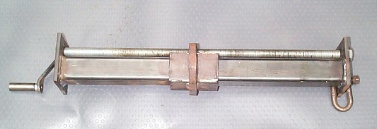
Bend the 10mm bar into a hoop that will fit over the saddle and tack weld it on. Check the hook on your engine hoist will sit comfortably in the hoop then fully weld it.
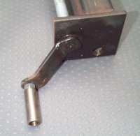
Drill the 16mm hole in the handle and bend it as shown in the diagram. Place a washer over one end of the threaded bar then fit the handle and weld it on to the bar. Weld the 12mm bar on to form the complete handle.
Fit a washer on the other end of the bar and screw the other two nuts on. Lock the nuts together, making sure the bar is free to turn. Grease the moving parts and your balancer is ready to go.
Note: do not paint the beam as the saddle will tend to bind, especially when under load.
To use the balancer hook it onto your engine hoist, then attach lifting ropes or chains to the front and back of the engine. Use shackles to attach the lifting ropes/chains to the 13mm holes and start lifting. As you start lifting you will have to move the saddle until you find the balance point.
Note: In true Locost tradition most of the dimensions can be altered to suit available materials. For instance you may be able to find some box that is a tight fit over the beam to make the saddle, or you could use a different thread on the threaded bar. The only real problem with a smaller thread is that it takes longer to adjust the balancer. Don't go less than M12 or it will be too weak.
This document and all images can be downloaded as one 226K zip
file for future reference
All images and text are copyright 2000 by Les Newell