There are a huge variety of commercial rail systems available. These include:
- Hardened steel shafts with recirculating ball bearings. These are very low friction and have little backlash. The shafts must be protected from sparks. Any sparks that weld themselves to the shaft will rapidly damage the bearings and seals.
- Hardened steel shafts with polymer plain bearings. These are cheaper but dust ingress is a problem.
- Linear slides with grooved bearings that run on a hardened, ground rail. Low friction, cheaper than recirculating ball bearings but again, dust and sparks can be a problem.
My solution was to use rubber sealed skateboard wheel bearings running directly on the box-section framework. It is crude and will make any professional CNC machine designer cringe but it does work!
Steel box-section is not accurate to a fraction of a thou like the purpose-made linear systems so the bearings have to be spring loaded to keep backlash to a minimum. Spring loading potentially reduces the stiffness of the system but the loads are very light so this is not a major problem.
The X axis
The X axis carriage uses a total of seven bearings. Two run on the top
of the rail and take the weight of the Y axis motor assembly. Two run on
the rear of the rail and keep the Y axis square to the X axis. The last
two bearings run on the front of the rail and are spring loaded to
prevent backlash. The seventh bearing is on the far end of the carriage
to take the weight.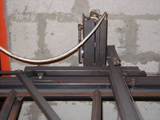 The
X axis carriage, showing the motor mount and adjustable brace to ensure
that the Y axis is at exactly 90 degrees to the X axis.
The
X axis carriage, showing the motor mount and adjustable brace to ensure
that the Y axis is at exactly 90 degrees to the X axis. The
rear of the X axis carriage, showing the fixed bearings and the Y
axis motor mount.
The
rear of the X axis carriage, showing the fixed bearings and the Y
axis motor mount.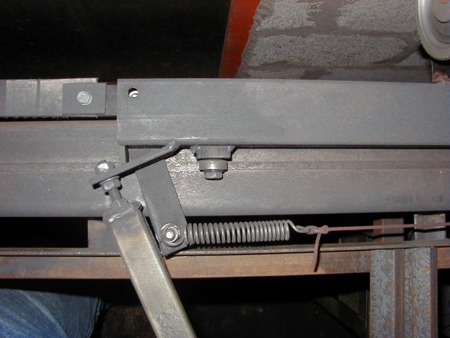 To
compensate for any variation in the width of the rail, the front
bearings are preloaded with a spring. You can also see the adjuster to
set the Y axis to exactly 90 degrees.
To
compensate for any variation in the width of the rail, the front
bearings are preloaded with a spring. You can also see the adjuster to
set the Y axis to exactly 90 degrees.The Y axis
The Y axis carriage is even simpler. It uses three bearings and two
steel rubbing pads (er.. actually screw heads). Two bearings run
on the front of the rail and one bearing runs on the back. The pads take
the weight of the assembly. The weight of the cutter head tries to
twist the carriage round on the rail, providing the preload for the
bearings. The unsightly chunk of angle sticking out is to increase
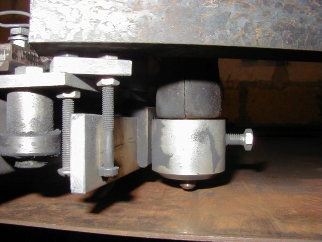
the preload because I had problems with the carriage lifting. 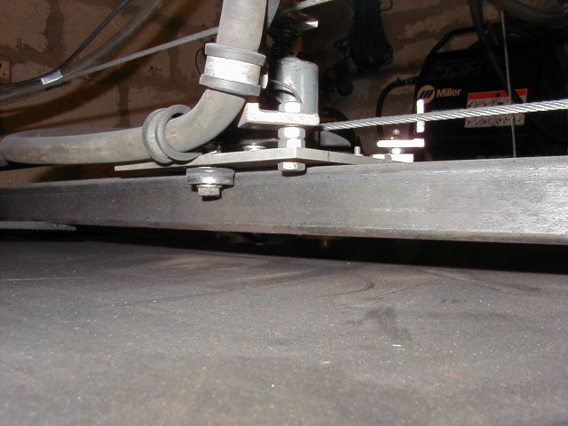 This is the rear of the Y axis carriage, showing the single bearing and
cable guides.
This is the rear of the Y axis carriage, showing the single bearing and
cable guides.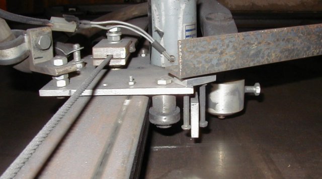 This is the Y axis carriage from the side. The front bearings sit lower
than the rear bearings so that the carriage doesn't twist itself off the
rail. The horrible bit of angle iron acts as a weigt to provide enough
load on the bearings to stop the carriage from lifting.
This is the Y axis carriage from the side. The front bearings sit lower
than the rear bearings so that the carriage doesn't twist itself off the
rail. The horrible bit of angle iron acts as a weigt to provide enough
load on the bearings to stop the carriage from lifting.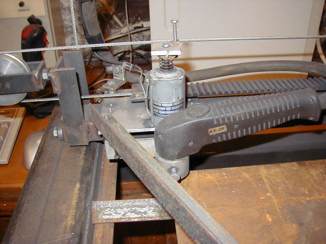 This
is the Y axis from the front. The cylindrical object just behind the
torch is the Z axis solenoid.
This
is the Y axis from the front. The cylindrical object just behind the
torch is the Z axis solenoid.The Z axis
The Z axis is very simple. When the arc is established a solenoid pulls the torch down onto the work. When the arc stops the solenoid is de-energised and a spring lifts the torch. The torch is a drag type so it is designed to work with the tip in contact with the work.
 The
torch fits in an aluminium cup which is attached to the solenoid. An
aluminium bar positioned between two bolts stops the torch from twisting.
The
torch fits in an aluminium cup which is attached to the solenoid. An
aluminium bar positioned between two bolts stops the torch from twisting.Back