A while back I bought a Colchester Triumph CNC lathe with a faulty
control. The owner of the lathe was quoted a huge sum to repair the control so I purchased it from him fairly cheaply. Once I got the 2.5
tonne beast home I found it wasn't in as good mechanical condition as I thought. The bed was more worn than I thought and the Z axis screw was a
bit rusty due to having been sitting for a long time. On further investigation I found that the central lubrication pump did not work. In
fact there was no way it had ever worked as it was missing a valve! The lack of oil explains the wear and rust.
I completely stripped the saddle and checked it over. The X axis
(cross slide) was in pretty good condition and the screw had obviously been replaced in the not too distant past. The sliding ways on the
bottom of the saddle were pretty bad but they are made of Turcite, an epoxy + PTFE compound. The saddle is simply held in place a few
millimetres off the bed then Turcite is injected into the gap and allowed to harden. You get an instant perfect fit with low friction.
Instead of rescraping you can simply sand it back to shape. It is still a slow process though. Sand a bit off, drop the saddle on and slide it
back and forth a few times, sand off the shiny bits and repeat.
As this is a fairly complicated machine and I wanted to do some clever stuff with the electronics, EMC was
an obvious choice for the control software. It is open source so if I
need any special functions I can write them myself. For instance the
buttins on the control panel are all interfaced through a custom module
for EMC.
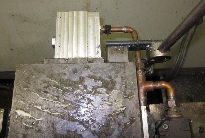
I
couldn't find any motor drives to suit the original Fanuc AC servo
motors so I fitted two large DC servos instead. of course shortly after I
did this someone brought out a drive that could run the original
motors! Servos need an encoder so the computer can keep track of the
motor's position. The Fanuc motors had these built in but the DC servos
didn't. There was very little room on the X axis and I ended up fitting
the encoder on the end of the screw in a waterproof housing. To get the
cables to the encoder and limit switches I used copper pipe. Copper pipe
works very well as it is water tight and tough while remaining fairly
compact.
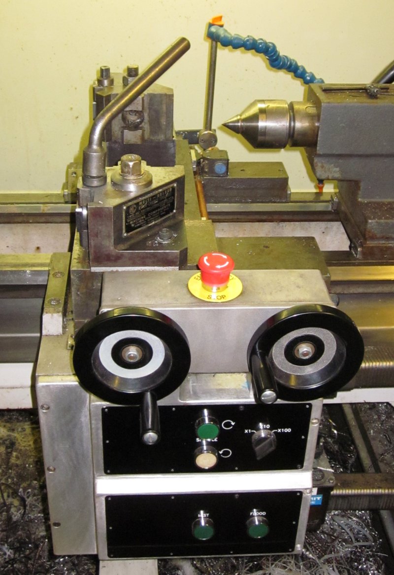
Originally
this machine was fully enclosed with a panel that projected through the
housing for manual control. I tend to do quite a lot of manual work so I
got rid of most of the enclosure and the large panel. Instead I fitted
electronic handwheels and a few useful buttons to control the machine.
On the top panel there are buttons to turn the spindle forwards and
reverse plus a handwheel sensitivity control. This allows me to quickly
switch between 1mm/turn for accurate work, 10mm/turn or 100mm/turn for
quickly traversing.
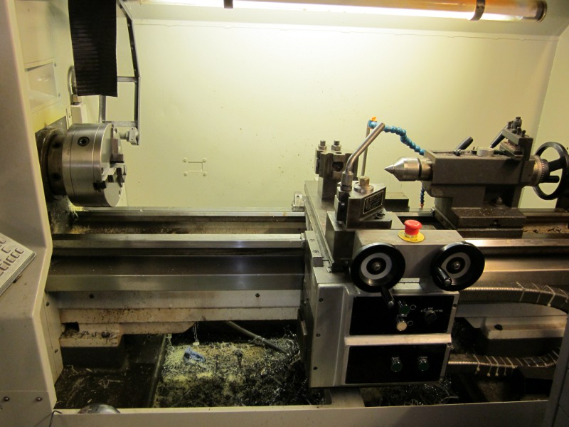
This
shows the whole bed. Originally you couldn't see most of this as it was
behind a big sliding door. The rail along the bottom is the last
remnant of the old enclosure. It used to be quite a bit higher and the
door slid along the top of it. There used to be a big casting where the
bottom panel is fitted on the saddle. This projected through a slot in
the cabinet and the original hand wheels and control panel were then
bolted to this casting.
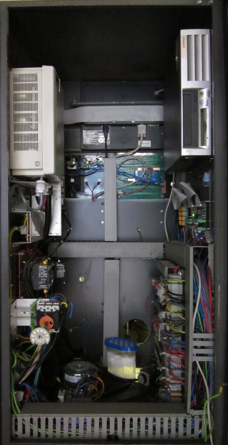
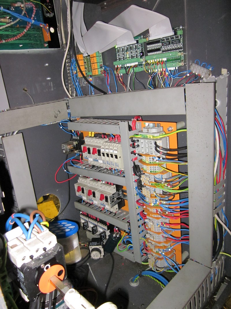
This
is inside the control cabinet. Towards the top right is the
computer. Below that are the contactors, fuses and overload trips. On
the left at the top is the 7.5kw spindle inverter. Below it is the mains
switching. In the middle at the top is the LCD monitor and below that
the two control panels. The object at the bottom with a blue lid is a
dehumidifier. As I live near the sea, damp is always an issue and
electronics don't like damp.
Here
is the wiring on the back of the front panels. The left hand panel has
power switches and assorted knobs. The right hand panel has a lot of
illuminated buttons. It was originally controlled by the Fanuc computer
but I added an adapter so I could control it using Modbus over a
USB connection.
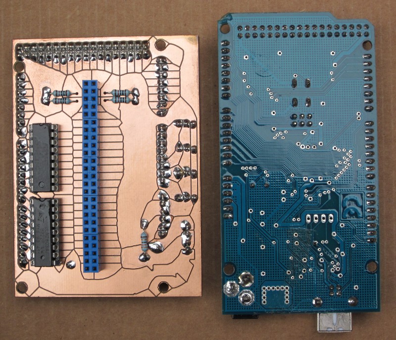
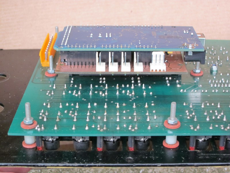
These two boards are make up the adapter. The right hand board is an Arduino which
is a small computer on a board and includes a USB connection. The
left hand board is my own design and interfaces the Arduino to
the panel. The tracks on this board were routed out on my Bridgeport CNC
mill. I used a clever piece of software called Visolate
which takes the output of a PCB design package and works out how to cut
it with the shortest cut paths possible. The tracks look a bit weird
but they all provide the correct connectivity.
This is the stack of boards assembled on the panel.
Here
is a closer look at the right hand side. As you can see there are a lot
of contactors, fuses and current trips in this machine. Towards the top
are the interface boards that handle the hand wheel encoders, buttons
and other inputs. The bunch of orange boxes towards the top left are
relays for various switching tasks. All of these boards are wired back
to a Mesa Electronics PCI interface board in the computer.
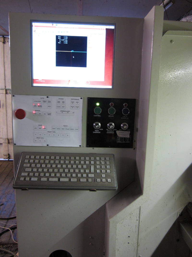
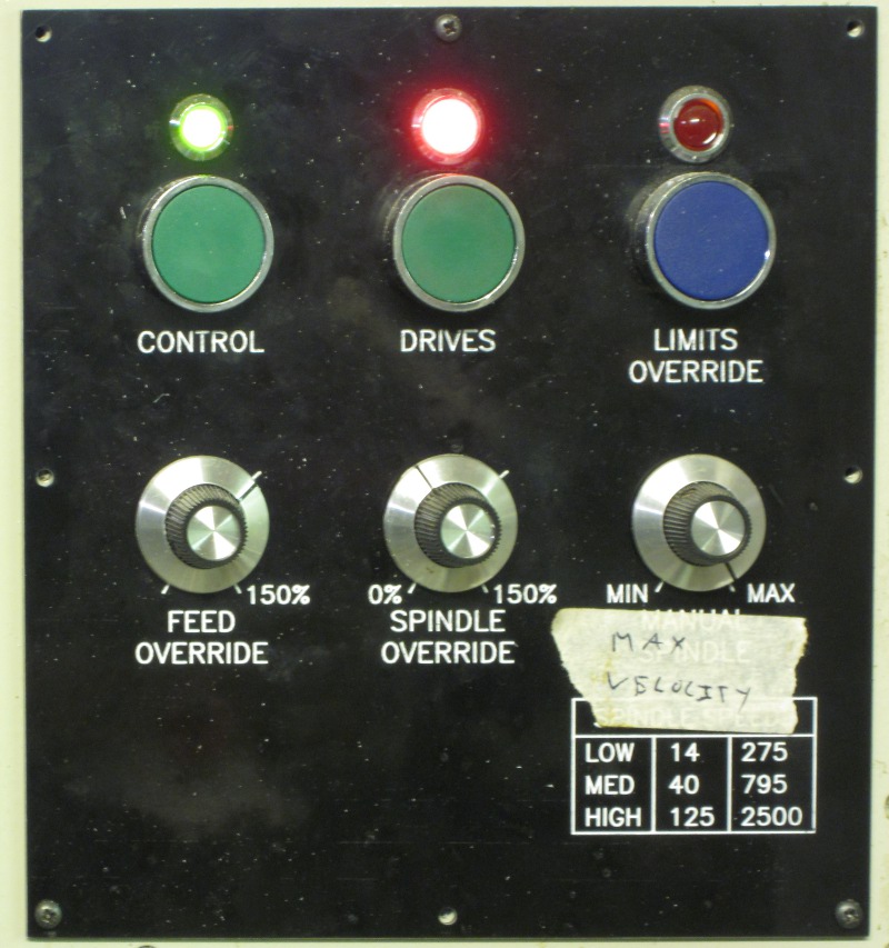
Moving round to the front, here are the main controls.
This
panel controls power on and various overrides such as feed rate and
spindle speed. The knobs are read by the Arduino on the left hand panel.
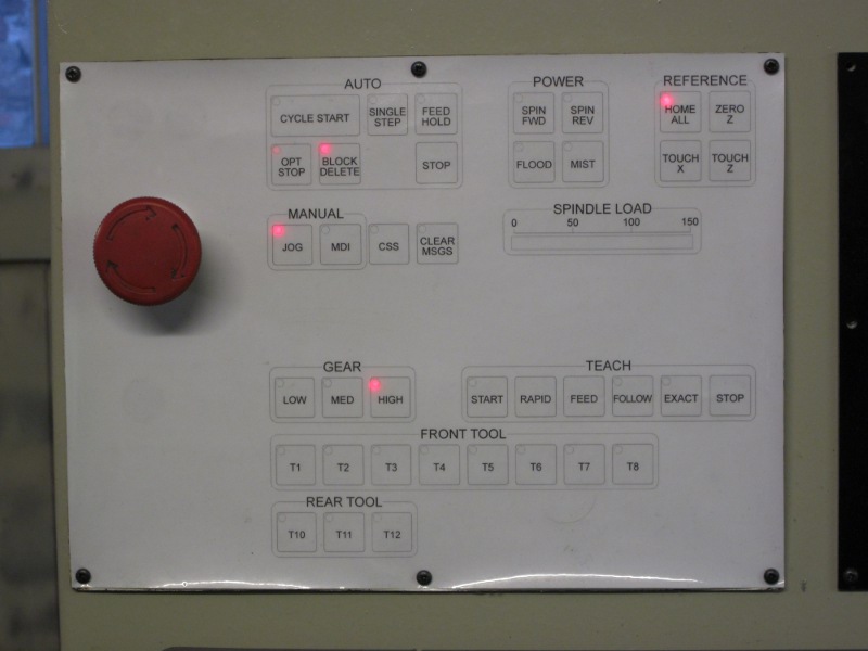
This
panel controls a lot of the lathe's functions. The label is just paper
with a plastic cover laminated over it. once I have finalised the layout
I'll print on self adhesive vinyl then laminate that to make a
completely water and oil proof label. A lot of the upper buttons will be
fairly familiar to users of CNC machines. The gear buttons control the
electronically operated gearbox. Teach doesn't do anything yet. I hope
to write a module to handle this at some point. Below we have
tool selection. These buttons aren't really relevant for CNC use but
they are really handy for manual use. First I enter the dimensions of
each tool. Each tool has a unique number. This only has to be done once
unless I move the tool in it's holder. Now when I change a tool I just
press it's button and the computer automatically applies offsets for
that tool. I can read the position of the cutting edge directly from the
screen.
Here is a video that I took a couple of years ago. I didn't have coolant plumbed in at that point.
Another video, showing one way of cutting a keyway on a CNC lathe.
 I
couldn't find any motor drives to suit the original Fanuc AC servo
motors so I fitted two large DC servos instead. of course shortly after I
did this someone brought out a drive that could run the original
motors! Servos need an encoder so the computer can keep track of the
motor's position. The Fanuc motors had these built in but the DC servos
didn't. There was very little room on the X axis and I ended up fitting
the encoder on the end of the screw in a waterproof housing. To get the
cables to the encoder and limit switches I used copper pipe. Copper pipe
works very well as it is water tight and tough while remaining fairly
compact.
I
couldn't find any motor drives to suit the original Fanuc AC servo
motors so I fitted two large DC servos instead. of course shortly after I
did this someone brought out a drive that could run the original
motors! Servos need an encoder so the computer can keep track of the
motor's position. The Fanuc motors had these built in but the DC servos
didn't. There was very little room on the X axis and I ended up fitting
the encoder on the end of the screw in a waterproof housing. To get the
cables to the encoder and limit switches I used copper pipe. Copper pipe
works very well as it is water tight and tough while remaining fairly
compact.